
Projects
Example Reports
VIBRATION ASSESSMENT
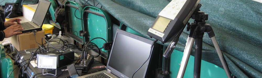
Scope of Report
To present the results of measurements of vibration from forges at ..., and from presses at ... . To estimate the vibration levels that may be expected at ... from the installation of forges.
1. INTRODUCTION
1.1 The ... intend to combine a number of operations that currently occur on separate sites, to a single site at ....
1.2 This includes the installation of large forge hammers and sensitive machining equipment.
1.3 This report estimates the vibration levels at the foundation of the sensitive machining equipment due to the operation of the forge hammers in order for vibration mitigation measures to be considered if it is determined that the vibration levels may adversely affect the sensitive machines.
2. THE SITE
2.1 Figure 1 shows a plan of the site.
2.2 Bays 6, 7 and 8, house a range of presses. The largest, a 12,000-tonne press, is situated in the middle of Bay 8.
2.3 Sensitive machining equipment is to be situated in Bay 4 (Mazak FH480 FMS machines). Bay 4 is currently empty.
2.4 A 12-tonne forge is to be installed at the eastern end of Bay 6. 6- and 2-tonne forges are to be installed in Bays 13 and 14. These forges currently operate on a site at ....
2.5 An additional sensitive CNC machine (Huron EX30) is to be installed at the western end of Bay 58. There is a 10,000-tonne blade forge in Bay 19.
3. MEASUREMENT PROCEDURE
3.1 All measurements were undertaken on 29th March 2001.
3.2 Measurements of the 12,000 tonne press at the ... site are used to determine vibration decay over this area of the site. Vibration measurements made of the forges at the site are then super-imposed on the decay model to estimate the vibration levels that may occur in Bay 4.
3.3 All measurements were undertaken using a four-channel laptop PC-based system running LabVIEW data-acquisition software. Three channels used a Kemo pre-amp and Bruel & Kjaer 4378 accelerometers with 2646 line drivers. The fourth channel used a Bruel & Kjaer 2635 charge amplifier with a Bruel & Kjaer 4366 accelerometer.
3.4 Vibration samples were 10-seconds long at a sample rate of 2560 Hz.
3.5 The accelerometers use magnets to attach to heavy, metal, spiked drums (~100mm dia). These are levelled on the measurement surface using screw adjustments.
3.6 See Figure 1 for approximate measurement locations.
3.7 12-tonne Press at ....
3.7.1 Three measurement locations were arranged in a line across Bay 4. The fourth location was in the middle of Bays 7 and 8, arranged to be both close to the press, and out of the way of workers.
3.7.2 The measurement locations were approximately at 30m, 74m, 110m, and 140m from the source.
3.7.3 Twenty samples were taken of transient pulses generated by the press. Ten samples were taken with the accelerometers orientated vertically, ten with the accelerometers orientated horizontally, radially from the source.
3.8 6- and 2-tonne Forge Hammers at ...
3.8.1 Both hammers were measured with the same measurement locations. These were approximately at 5m, 10m, and 20m, from the 6-tonne hammer and 10m, 20m, and 30m from the 2-tonne hammer. It was not possible to arrange the measurement locations over a larger distance.
3.8.2 12 samples were taken - 7 vertical and 5 radial. Each sample contained a number of impacts.
3.8.3 At the time of the survey the largest forge hammer at (the 12-tonne) was not in operation.
3.9 10,000-tonne Blade Forge at ...
3.9.1 The accelerometers were arranged in pairs to simultaneously measure vertical and horizontal vibration.
3.9.2 One pair of accelerometers was positioned approximately 5m from the blade forge, the other pair at the western end of Bay 58, where a Huron EX30 CNC machine is to be installed.
3.9.3 5 impacts were measured.
4. RESULTS
4.1 All results were processed using Matlab to determine peak magnitude and frequency information for each sample. A selection of time histories and spectra are shown in Appendix A. Note that different scales are used for the ordinate of the time histories in order to show the waveforms as clearly as possible.
4.2 Prediction of Vibration due to Installation of Forges at ...
4.2.1 A summary of measurements of Bay 4 and forge hammers at ... are shown in Figures 2(a) and (b).
4.2.2 Using the decay model based on site measurements, the predicted ground vibration in Bay 4 due to installation of 6- and 2-tonne forge hammers in Bays 13 and 14 is 0.0726 m/s2 in the vertical direction and 0.0536 m/s2 in the horizontal direction.
4.2.3 However, it is important to note that there are a number of factors that could result in a higher vibration than that predicted. Factors must therefore be applied to the value in 4.2.2 to account for variations in soil properties between and throughout each site; variation in foundation response between the existing foundations measured at and the foundations to be installed at ...; and local ground resonance's that may occur.
4.2.4 We suggest that a factor of 2.5 is appropriate, with confidence of 80% that the predicted vibration levels will not be exceeded. These factored levels are therefore 0.1815 m/s2 in the vertical direction and 0.134 m/s2 in the horizontal direction. The vibration levels could be reduced by such variations, but we consider that it is safer to consider these 'worst case' situations.
4.2.5 The dominant frequency seen in the impact measurements across the western end of the site is 9 Hz. If it is assumed that this frequency is dominant in the proposed installation, a dynamic displacement in the ground of 0.057 mm in the vertical direction, and 0.042 mm in the horizontal direction, could be expected.
4.2.6 However, it would be prudent to consider a range of frequencies, as this influences the displacement that occurs. For a frequency range of 7 to 11 Hz, a range of dynamic displacements from 0.038 - 0.094 mm in the vertical direction and 0.028 - 0.069 mm in the horizontal direction would be expected to occur for the same values of acceleration
4.2.7 It is also important to note that this survey is a snapshot of vibration due to the forging hammers working on one particular job. Variations in vibration occur due to the type of work being undertaken.
4.2.8 Also note that the predictions do not take account of the 12-tonne forging hammer.
4.2.9 These predictions do not take into account the possibility of simultaneous impacts from two or more machines. However, this is considered to be highly unlikely.
4.3 Huron EX30 CNC Machine in Bay 58
4.3.1 The maximum vibration levels measured at the proposed location of the Huron CNC machine in Bay 58 due to the operation of the blade forge were 0.037 m/s2 in the vertical direction and 0.028 m/s2 in the horizontal direction.
4.3.2 However, as the machine is at a similar proximity to the proposed forge hammers as the FMS machines are, similar vibration levels could be expected.
4.3.3 Therefore, we suggest that the levels shown in 4.2.4 are applied to this machine.
5. VIBRATION LIMITS
5.1 Mazak FH480
5.1.1 Mr ... of Mazak informs us that they do not have any vibration limits for their machines. Mazak UK have contacted their Japanese managers an found that they do not have any limits either.
5.1.2 However, we are informed that the machines can work to an accuracy of around 0.01 mm. As dynamic displacements in excess of 0.05 mm could be expected in the ground at the base of the machines, the vibration is likely to adversely affect the accuracy of the work, and hence isolation will be required.
5.1.3 The Mazak machines have a foundation to protect them from 'normal' environments - e.g. footfall vibration of workers, fork-lift pass-by etc. This is in the form of an inertia block on a resilient strip. We recommend that this foundation system is replaced with one designed with the low frequency vibrations in mind (i.e. larger inertia block on softer springs).
5.1.4 Huron EX30
5.1.4.1 Mr ... of the Carne Group (suppliers of Huron machines) informs us of the following:
- the EX30 must be installed on the manufacturer's recommended foundation to deal with the forces generated by the machine itself,
- the machine on it's recommended foundation is designed to protect the precision of the machine from vibration in a 'normal' operating environment - e.g. footfall vibration of workers, fork-lift pass-by etc.
- Huron recommend that the machine is isolated for any condition more severe than this.
5.1.4.2 Therefore, in this situation, where vibration levels are likely to be in excess of those in a 'normal' operating environment and at a lower frequency, some form of additional isolation will be required.
6. VIBRATION MITIGATION MEASURES
6.1 It is important to recall that the dominant frequencies of the vibration measured at Road were around 9 Hz. These are particularly low frequencies and can be difficult to isolate.
6.2 Vibration isolation can be applied to the source (in this case the forge hammer foundations) or to the receiver (foundations of the sensitive machines).
6.3 As there is vibration from existing machines on the site, which will not be isolated, it is thought that isolation of the sensitive machines is more appropriate.
6.4 Isolation of sensitive machines from external low frequency sources is in the form of an inertia block (usually a large block of concrete) mounted on soft springs. The inertia block is usually installed below floor level due to it's size, so that the machines are at their normal height.
6.5 There are limitations to the degree of isolation that can be achieved at such a low frequency, so it may be necessary to isolate the source if the required isolation cannot be achieved at the receiver.
6.6 In this case, the forging hammers would be mounted either directly or through an inertia block on soft springs, to a lower foundation in contact with the soil. The design of the foundation in contact with the soil will require static and dynamic soil properties.
7. SUMMARY
7.1 Vibration due to the operation of the proposed forging hammers at Road is predicted to adversely affect the precision operation of a sensitive CNC machine and a number of FMS milling machines that are also proposed for the site.
7.2 Isolation systems are recommend for both the CNC machine and the FMS milling machines.
7.3 The isolation systems are to be in the form of an inertia block on soft springs.
7.4 The CNC machine requires the manufacturer's foundation to deal with internally generated forces, so the isolation system must be mounted beneath this.
7.5 The FMS milling machines have an isolation system of a similar form, but tuned to a higher frequency. This foundation is to be replaced with one tuned with respect to the low frequency conditions on site.
7.6 If sufficient isolation cannot be achieved by isolating the machines, the hammers must be isolated as well. In this case, a hammer would be mounted on soft springs on top of the foundation. The foundation should be considerably stiffer than the ground in order to achieve effective isolation. This may involve piled foundations.
7.7 The extent of vibration control required depends upon the vibration limit that is assumed for the sensitive equipment. It appears that the sensitivity of the equipment will need to be estimated, where possible from first principles.
7.8 Alternatively it would need to be related to other similar classes of sensitive equipment. Clearly it would be quicker and more economical if the designers of the sensitive equipment, familiar with their equipment develop this. If this is not possible, then we would need to obtain their engineering drawings and produce some numeric target to aim for, relating it to certain physical processes that take place. Alternatively, it may be possible to develop limits from vibration trials on their equipment, or identify a site where they are exposed to transient vibration from presses, although similarity of the low frequencies for direct comparison would be necessary.
7.9 The design of vibration control for the foundations for both the sensitive equipment and forges will need to be developed, in association with quantification of sensible target limits. We will be happy to indicate a programme and time costs.