

Projects
Industrial Sponsorship
Dynamic Performance Investigation of Base Isolated Structures
By Ather K. Sharif
2.1 Introduction
This chapter describes mechanisms that give rise to vibration from the passage of trains, describing how the disturbance propagates and is affected by features in the transmission path.
2.2 Source Characteristics
The impact of vibration from railways became the subject of public concern upon the introduction of underground railways in London at the turn of the Century. This led to the Board of Trade appointing a Committee, chaired by Lord Rayleigh, to report in 1902 concerning 'Vibration produced by the working of traffic on the Central London Railway'. Whilst the trains would originally have been hauled using steam locomotives, this study related to the time when electric traction was in use.
Whilst vibration would not have been an unfamiliar occurrence at the time, being evident upon the passage of horse driven carriages on cobble stone streets, strong complaints of vibration arose from occupants of buildings along the route of the railway. The committee were satisfied by personal observation that the levels felt in many of the houses was sufficient to cause a serious nuisance. Instrumental observations of vibration in terms of displacement were made. These can be equated to velocity using the predominant frequency reported as 15Hz, which gives a vibration level in the basement and solid floor of houses at around 0.5mm/sec, and on upper floors at around 2mm/sec.
It was recognised at the time that if the track were perfectly straight, wheels perfectly round, and elastic support uniform, then no dynamic forces would arise. All that would happen is that the track would adopt a displacement profile similar to Figure 2.1.
It was recognised that as train speeds (typically 20 to 30mph) of the time were well below wave propagation speeds in the soil, this would be the quasi-static shape of track displacement, which would move with the axles and no vibration would arise. It was anticipated that when train speeds exceed wave propagation speed of the ground, shock waves would arise as has been recently studied in detail by Krylov (1994a).
But the vibration that arose was readily understood as being caused by the mass of the vehicle being made to follow the alignment of the track, where in practice the rails were found not to be straight, and the wheels were found not to be round. This would cause the moving mass of the vehicle to be subject to accelerations to make it follow the alignment of the track and this would result in dynamic forces. Similarly the wheels would traverse steps in the rail at joints, leading to impacts.
It was also realised that the actual support stiffness was not uniform. On the underground at the time, sleepers were laid longitudinally taking periodic support off the flanges of the tunnel lining. It was these flanges which offered higher support stiffness when the wheel was directly over, but in between, the sleepers offered smaller stiffness, to which the contribution of rail stiffness became more important. Thus it was seen that vibration would be a function of the distance between discrete 'stiffer' supports (such as sleeper spacing in normal ballast track), axle spacing and train speed.
Observations showed the worst part of disturbance to be due to locomotives as distinct from the carriages. The overall mass of the locomotive was 44 tons, and the passenger carriage 14 tons. Part of the mass was borne by the axle directly (unsprung mass) and the other part was borne by springs taking support off the axles (bogie), summarised in Table 2.1.
Table 2.1 Mass per axle of various classes of rolling stock (Mallock, 1902)
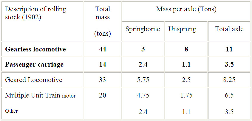
This focused attention on the much larger unsprung mass of the standard (gearless) locomotive, which was 8 tons per axle, whereas the passenger coaches had an unsprung mass of 1.1 tons per axle. In contrast the spring borne mass was similar in the two cases.
There were as a result two alternative designs of the locomotives, which would have reduced unsprung mass, shown in Table 2.1. One system referred to as 'geared locomotive' involved using gearing, such that the electric machinery was no longer mounted directly on the driving axles, which reduced the unsprung mass to 2.5 tons on each axle. The other system was referred to as 'multiple unit', in which the locomotive is not distinct, but carried at one end of two or more passenger cars, which gave a reduced unsprung mass on each axle under the motor of 1.75 tons. The ground vibration was said to be reduced with reduction in unsprung mass.
Key findings of the study were therefore that vibration magnitude was directly related to the size of the unsprung mass and the more this could be reduced the greater the reduction in ground vibration. Factors such as the smoothness of the rails and roundness of the wheels, which were subject to direct measurements, were shown to be important. Significantly the study also indicated that changing stiffness in the support of the rail, such as the effects of sleepers and their spacing should be evidenced in the measurements. In fact wear in the rail was found to match the spacing of supports. It therefore concluded that a higher rigidity of rail would be desirable. The study concluded that new ‘multiple unit’ type locomotives with reduced unsprung mass would lead to acceptable vibration levels, although noted noise may still be detected at night.
The report of Rayleigh et al (1902) represents not only the first, but a very significant investigation into the problem of vibration from railways. A great deal of credit should go to Mallock, who is referred to by Lord Rayleigh as the principal investigator. Since that date, there has been growing interest in the effect of moving loads, primarily in the context of trains traversing bridges (see Frýba, 1972). Our understanding today of the source characteristics (Saurenman et al, 1982; Frederick, 1987; Ford, 1987; Auersch, 1990; Krüger, 1990, 1992; Rücker, 1995a,b; Melke, 1995; ORE D151 Rep 12, 1989) are in principle the same, although the detail by which we measure vibration and test the effect of various parameters has grown. Some specific aspects of more recent findings are worthy of mention.
Figure 2.2 shows vibration spectra measured at the side of a BR track (cwr) for a given freight train, which was made to pass by at different speeds. The frequency of the peaks in the spectra were identified using narrow band analysis and assigned the nearest third octave values which were plotted against train speed, producing a Campbell Diagram (ORE D151 Rep 1, 1981). The diagram shows a series of parallel lines which are assigned a 'characteristic wavelength', obtained from train speed divided by the frequency. The characteristic wavelengths were then explained as recognisable features, such as: 0.7m corresponding to sleeper spacing; 1.78m due to characteristics of rail straightening process (undertaken in a machine which has rollers spaced at 1.78m); 6.1m as a third of rail length (18.3m) and half vehicle length (12.2m). No adequate explanation has ever been given for the 2.48m wavelength obtained in that survey. Such diagrams at other sites have also shown horizontal lines, which indicate features that are independent of train speed, therefore representing natural frequencies of the system.
Increasing speed of a train can cause an increase in vibration and groundborne noise. Experiments in the Paris Metro have shown that an increase in train speed may cause larger changes in high frequency components closer to the source in the tunnel, whereas further away, in wayside buildings the changes were less obvious as high frequency components are better attenuated. Increases of 3dB (vibration) and 3dBA (groundborne noise) were reported for a speed increase from 20 to 60km/h (ORE D151 Rep 9, 1984).
Train speed effects do not vary linearly. Figure 2.3a shows upper bound tunnel wall vibration spectrum (from New York, Toronto and Paris Metros for jointed rail on stiff fasteners with reference speed of 56km/hr) with third octave band levels subject to the speed correction of Figure 2.3b (Nelson & Saurenman, 1983; Remington et al , 1987).
Strong vibration can arise if the excitation frequency associated with the sleeper passing frequency matches the natural frequency of the unsprung mass on the track/soil resilience. Because sleeper passing frequency increases in proportion to train speed, vibration may be more noticeable at certain 'critical' train speeds. Figure 2.4 shows such an example, which in fact arises at a low train speed. Therefore a speed restriction at this site would lead to higher vibration levels (Griffin and Stanworth, 1985).
Greer (1996) has examined the speed dependent effects in greater detail. The measured behaviour has been explained as a superposition of various effects which dominate at different speeds, summarised in Figure 2.5. There is now growing interest in the effect of higher train speeds (see Krylov, 1995a).
Generally low frequency peaks in the spectrum (<50Hz) are associated with sleeper passage and axle passage frequencies which are dependent upon train speed. These low frequencies, which are harmonic in character, tend to be the main source of perceptible vibration. Whilst higher frequencies primarily related to groundborne noise perception are associated with inertia forces of the accelerated unsprung mass due to rail/wheel roughness, are more random in character, and the position of the spectral peaks unlike their amplitude are independent of train speed.
The rolling stock has changed and there is a diverse range. They may consist of a 'Diesel Electric Locomotive', where the diesel engine powers electric traction motors for propulsion, or the locomotive may be an 'Electric Locomotive' where traction motors obtain power from either an overhead wire collected from a Pantograph, or via the ‘third rail’. The rolling stock may be in the form of an 'Electric Multiple Unit', where there are a set of electrically powered passenger carrying rail cars.
Rolling stock unsprung masses (typically 1 to 3 tonnes), suspension and damping details all vary, and about the only thing that remains constant is the Standard Gauge of 1435mm for the UK. It has been shown by Grassie (1984) that the contact flexibility arising between the wheel (typically 350kg) on the rail, through a contact patch (typically 14mm x 10mm) leads to a natural frequency of around 275Hz. For most calculations of groundborne noise and vibration this contact flexibility can be ignored, expect where airborne noise is relevant (Remington et al, 1975). Wheelset axle bending fundamental frequencies are reported to be in the range of 50Hz to 90Hz (Melke, 1995). Rigid body natural frequencies of the carriage (secondary suspension) are reported to range from 1Hz to 3Hz, for the bogie (primary suspension) from 6Hz to 10Hz, and the natural frequency of the wheelset (unsprung mass) on the ‘track/soil spring’ range from 55Hz to 150Hz (Rücker, 1995a). Flexing modes of the carriage itself are also relevant.
Typically, freight wagons have the highest unsprung mass, with Metro trains having the smallest, and reducing unsprung mass has already been shown to be a significant factor in reducing ground vibration (Mallock, 1902). Primary suspension stiffness is an important vehicle factor (see Figure 2.1), because a reduction in stiffness leads to a reduction in ground vibration (Saurenman et al, 1982), by decoupling bogie and carriage mass from unsprung mass and thus ensuring that this is small (Kraemer, 1984).
Suspension details depend amongst other things upon ride comfort, and interestingly, for trains in tunnels there is requirement to reduce the dynamic envelope of the train to safely fit within the tunnel, which is itself minimised for economy of construction (usually achieved by using a relatively stiff vehicle suspension). Load sensitive friction dampers on freight wagons, which are parallel to the springs have been reported to stick, because the small track and wheel irregularities are insufficient to overcome the friction force in the damper. This causes the full 25 tonne axle load to appear as the unsprung mass, leading to very high vibration levels (Frederick, 1987).
Rail cross-section has only been subject to three changes since 1848 to date (see Figure_2.6). This demonstrates that the rail industry is relatively slow to change, due to immense capital expenditure and programme implications that can arise on a live network. There are now plans for a heavier rail section, to cater for increased axle loads predicted on mainline tracks from the current maximum of 25.5 tonnes to 30 tonnes in the near future (Parker, 1998).
A wide variety of track systems are now available, from varied rail fastenings to variations of the standard ballast track, which may comprise booted sleepers, resilient ballast mats or ballastless track with resilient baseplates and/or floating track slabs which are discussed fully in Chapter 4.
Joints are now formed using welds (cwr), to alleviate the impact effects at joints, but points (switches) are still a source of higher vibration even though train speed through these should be slower than permitted on mainline. It should be noted that even though welds are used to make rail joints, differential wear at the weld due to variations in hardness can cause the weld zone to become raised in service by 0.08mm, and therefore be a source of impact (Frederick and Round, 1985). Wheel-flats can develop during braking and cause impact between wheel and rail. It has been suggested that depending upon the length of wheel-flat and train speed, the wheel 'flies' over the flats. Wheel slide protection systems are in use to reduce formation of wheel-flats in service.
Experiments have been undertaken in the Paris Metro to examine the influence of the condition of wheel tread (ORE D151 Rep 9, 1984). This showed that a train with re-profiled wheels cause the lowest levels of vibration and noise in a neighbouring property, compared to: normally worn wheels; those with wheel-flats arising in service during skidding; and those with artificially created wheel-flats. As a guide the re-profiled wheels caused building vibration that was about 6dB less and in terms of groundborne noise about 3dBA less, compared to the worn wheels in normal service. With wheel-flats created in service during skidding, this caused an increase in vibration level of about 2.5dB and 5dBA higher in terms of groundborne noise compared to the situation using normally worn wheels. Whereas the wheel-flats created in service during skidding did cause a significant increase in vibration and noise, the wheel-flats that were created artificially using a grinder did not significantly increase the overall vibration level. However the impacts could be detected audibly, were of high frequency energy, which was quickly absorbed through the ground. The difference has been attributed to the fact that the wheel-flats which arise in service during skidding cause a rearward flow of material as it is worn, which creates a swelling behind the wheel flat, which may be 1mm high, whereas the grinder simply removes the material.
The quality of the rail profile is as important as that of the wheel. Long wave corrugations have wavelengths in the range 150mm to 1200mm with peak to peak amplitude of 3mm in severe cases (Clark, 1985). Short pitch rail corrugations (40 to 70mm wavelength) cause high frequency periodic forces, which can have significant affects on the track and its fixings, despite the shallow depth (typically BR track peak to peak 0.1mm and in extreme cases 0.2mm) of this short wavelength rail corrugation. Short pitch rail corrugations are more significant as a source of airborne noise rather than groundborne noise and vibration (Frederick and Round, 1985).
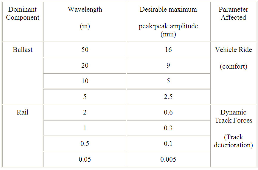
The minimum permissible track standard will depend upon the type of traffic, passenger/freight and its speed. For passenger trains, travelling at 200km/h, Selig and Waters (1994) present limits on vertical smoothness in Table 2.2.
Table 2.2 Desirable Smoothness Limits at 200 km/h (Selig and Waters, 1994)
Measurements of rail roughness and wheel roundness have grown. Track monitoring can range from standard optical surveying techniques with a level and staff to lasers, which can achieve an accuracy of ±1mm, with a range up to 600m. Track survey cars permit continuous measurement of level and alignment. Such methods are suitable for measuring overall track alignment, but do not resolve short wavelength track geometry.
British Rail has developed a 'FROG Trolley' to measure absolute, unloaded longitudinal vertical profile of a track, for wavelengths comparable with sleeper spacing. It consists of a trolley, where the wheel span matches sleeper spacing, and is positioned over the sleepers at the start of the measurement. Inclinometers measure angle of tilt both longitudinally and across the rails. The trolley is then pushed along to the next sleeper by hand, with inclinometer readings stored to memory. A longitudinal rail profile is thus obtained by placing the snapshot readings at each sleeper sequence end to end (see Selig and Waters, 1994).
RM1200E is a modern device for measuring rail roughness, developed by MüllerBBM (1998) in Germany. The displacement pick up has a measurement range of ± 2mm with detection down to 0.2m m r.m.s. A significant point to note is that systems such as this are suitable for measuring short wavelength features. It has a sampling wavelength of 0.48mm, and a limit on resolving wavelengths down to 1.23mm. The unit is 1.2m long and therefore will itself act like a high pass filter ignoring longer wavelength features.
There now exists a draft International Standard for the reporting and measurement of rail track geometry (DIS 9629, 1996) and there exists an International Standard for the measurement of vibration in railway tunnels (BS ISO 10815, 1996).
2.3 Propagation Characteristics
Ground vibration exists as a variety of waves, each with characteristic particle motion.
Poisson (1831) is accredited for proving that a homogenous isotropic elastic solid of unlimited extent can transmit two kinds of waves (body waves), longitudinal (P wave) and transverse (S wave), with different velocities. Stokes (1849) proved that the longitudinal wave is a wave of irrotational dilatation, and the slower transverse wave is a wave of equivoluminal distortion.
Lord Rayleigh (1885) investigated the behaviour of waves that arise upon the plane free surface of an infinite homogenous isotropic solid (elastic half-space). This was studied in greater detail by Lamb (1904) who described the surface disturbance due to a vertical impulse, reproduced in Figure 2.7.
The Rayleigh waves are confined to a superficial region, to a thickness that is comparable to their wavelength. They cause particles in their path to undergo elliptical motion in a retrograde sense, as opposed to prograde motion found in gravitational surface waves in liquids. The vertical component is theoretically larger than the horizontal component, which is parallel to the direction of wave propagation, and depends upon the Poisson ratio of the material. The velocity of propagation of Rayleigh waves is smaller than that of body waves.
Lamb (1904) himself noted that the theoretical surface disturbance (Figure 2.7) lacked the characteristic long succession of to and fro motion seen in seismogram records, and also that the vertical component of the Rayleigh wave is actually relatively small compared to the horizontal radial component. These shortcomings are due to idealisations of Lamb's model, which fail to be met in practice due to layering and dispersive effects in the ground. Ewing et al (1957) refer to model studies by Tatel (1954) where idealisations of a homogenous isotropic elastic half-space were better met, showing surface disturbance to resemble all the characteristics predicted by Lamb.
Amplitude of the elastic waves diminishes with increasing distance from the source (r), as it encounters a larger volume as it propagates, which is referred to as geometric attenuation (sometimes inappropriately as geometric damping). For body waves, which propagate on a hemispherical wave front from a point source, the amplitude diminishes in proportion to 1/r, except along the surface where it diminishes in proportion to 1/r2. The Rayleigh waves propagate from a point source on a cylindrical wave front, and the amplitude diminishes as 1/Ö r . From a line source, these attenuation values are quoted as 1/Ö r for body waves, and 1/r1.5 for body waves along the surface, and independent of r for the Rayleigh wave (see Lamb,1904; Ewing et al, 1957).
A train can either be considered as a point source or a line source, depending upon distance from the source. Gutowski and Dym (1976) indicate that a train can be modelled as a line source in the 'far-field' (where point sources "coalesce" so as to been seen as a line source), for distances up to (1/p ) times the source length; which for a train of 100m length, equates to a distance of up to about 30m. In reality, the source may need to be considered as a superposition of a line and point sources (Verhas, 1979).
The vibration amplitude of waves also decays with distance from the source due to material damping (see Kolsky,1953; Ewing et al,1957; Hardin and Drnevich 1972a,b). Material damping can lead to a change in the time history, with lower frequency motion predominating with distance from the source. Such observations in the field have been used by some workers to imply that material damping increases with frequency (ORE D151 Rep 3,1983; Frederick, 1987), which indicates viscous type damping (energy dissipated per cycle increases linearly with frequency). It is important to recognise that high frequency vibration is of shorter wavelength compared to low frequency vibration, such that at a given distance from a source there will be more cycles of high frequency vibration. As there are more cycles of high frequency vibration, more energy is dissipated into heat, during each hysteresis loop, compared to the smaller number of cycles of low frequency waves. This can give the false appearance that material damping increases with frequency. It is therefore better to refer to material damping as proportional to the number of wavelengths (see Verhas, 1979).
The mechanism of energy dissipation in soils is reported by some workers to be independent of strain rate and therefore frequency (see Hardin and Drnevich 1972a,b; Sarma and Breitwieser, 1991). The term ‘ideal’ hysteretic damper has been used (Crandall, 1991) to describe a ‘linear’ model where energy dissipation is independent of frequency. Hunt (1988) indicates that the nature of soil damping may depend upon the type of soil and strain, and shows soil damping was viscous for the saturated cohesive soils in his study related to traffic induced ground vibration. He also highlights that data on soil damping is related to shear deformation and that nothing is quoted for changes in volume, although notes that losses associated with the latter are considered to be smaller. Sarma and Breitwieser (1991) concede that there may be a strain rate effect (viscous component) at very small strains. Elgamal et al (1995) indicate that a viscous component was observed in their site tests at any given strain level.
Hardin and Drnevich (1972a) using experimental data showed that increasing the amplitude of shear strain causes shear modulus to decrease rapidly, whilst damping ratio increases. This shows that soils are non-linear. Such non-linear properties associated with amplitude of strain are difficult to accommodate in a theoretical model, and may in certain circumstances be an unjustified refinement given all the other uncertainties (see Sarma and Breitwieser,1991; Sarma 1994). Fortunately for railway-induced vibration propagation, linear behaviour (Prange, 1977a) can be reasonably assumed for the very low shear strains involved ( <10-5).
Internal friction in a material has been shown theoretically by Knopoff (1956) to be one of the factors responsible for pulse broadening with distance. Whilst a pulse source can cause a train of sinusoids due to layering effects (Love, 1911), dispersion can also modify a pulse into a train of sinusoidal waves, whose period varies along the train.
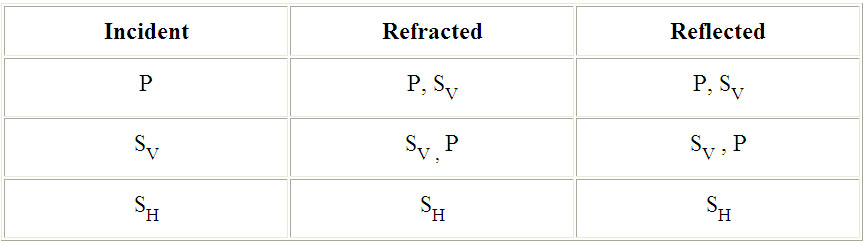
Layering of the ground has important implications. Knott (1899) and Zöppritz (1919) give accounts of the distribution of wave energy at boundaries. Richart et al (1970) reviewed the work of Zöppritz, and summarise that in a layered soil, the magnitude of body waves which are refracted and reflected depends upon the angle of incidence, the ratio of wave velocities in the two media at the boundary, and their respective densities. Wave conversion can also arise at the boundary, where it is important to resolve the S wave into its vertical SV and horizontal SH components, as shown in Table 2.3.
Table 2.3 P & SV,H Wave conversion at boundary of two solids (Richart et al 1970)
Love (1911) proved the existence of a new type of surface wave in a superficial layer overlying an elastic half-space, in which motion is transverse to the direction of wave propagation. This Love wave, as it is called, can only exist if the shear wave velocity in the superficial layer is less than the shear wave velocity in the next lower layer, and the velocity of the Love wave lies between the two. Love waves have been described by others (Leet,1938; Ewing et al,1957) as a horizontally polarised shear wave trapped in a superficial layer propagated by multiple total reflections. Stoneley (1924) showed that Love waves could also exist in an internal stratum.
Stoneley (1924) also examined the nature of waves that can arise on the interface between two solid media, and showed it to be a generalised Rayleigh wave, which exists on the interface when the S wave velocities in the two media are similar. These waves that propagate along the interface are referred to as Stoneley waves, and propagate at a velocity between that of the Rayleigh and S waves in the denser media and their amplitude decreases exponentially with distance from the interface. The Stoneley waves also diminish with distance as they propagate according to 1/Ö r (Ewing et al 1957).
An incident P wave can be critically refracted such that it travels along the interface in the medium with the higher P wave propagation velocity. Here it remains as a P wave but can lead to the development of what is called a head wave in the surface layer (see Richart et al ,1970).
Whilst an interface between two solids has been discussed, a water table can also act as an interface leading to reflection and refraction, and some dynamic properties of the soil can be altered when saturated by water (see Biot, 1956a,b,1962; Ishihara,_1967; Richart et al, 1970). Biot (1956a,b) has theoretically shown that a fluid saturated porous solid can sustain two types of P waves, with different propagation velocities, are dispersive and that each of these waves involve coupled motion in the fluid and the solid.
Miller and Pursey (1954,1955) determined the proportion of total input energy, from a vertical oscillating circular footing on an homogenous isotropic elastic half-space, that is transmitted away as P waves, S waves and Rayleigh waves. They considered a (single element radiator) point source and a (three element radiator) distributed point sources which are shown in Table 2.4. The latter 'three element radiator' configuration was analysed to study the behaviour of a source similar to an electrodynamic shaker unit supported on three points, on a circle of 450mm diameter described by Evison (1951) for geophysical prospecting.
Table 2.4 % of total energy transmitted by three elastic waves (Miller and Pursey, 1954)
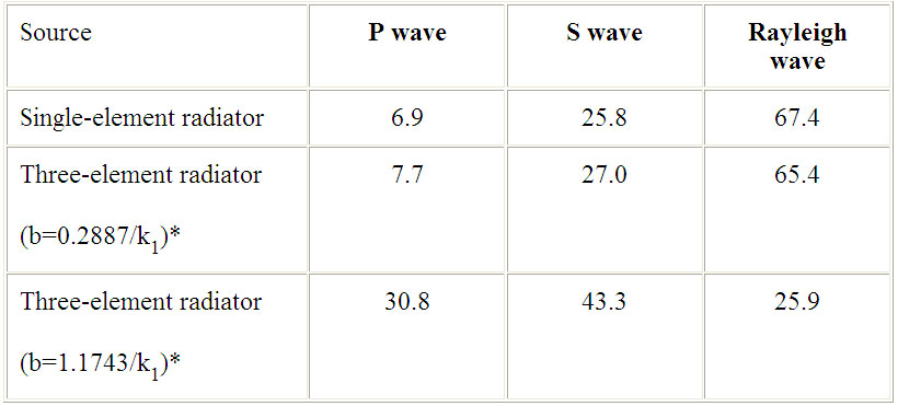
* where: radiator element lies on the vertices of an equilateral triangle fitting a circle of radius b, k1=2p /l , l =wavelength of P wave
Here we see that for a single point source the majority of the energy is transmitted away as Rayleigh waves. However it is significant to note that at a given frequency and therefore wavelength, three individual point sources can be arranged, such that when they are distributed equally along the circumference of a circle of radius b, an equivalent distribution of energy amongst the three wave types can be achieved to that obtained from an individual point source (compare row one and two of Table 2.4). However a fourfold increase in this radius can change the dominance from Rayleigh waves to Body waves (compare row two and three of Table 2.4).
The dominance of a particular wave type is therefore theoretically shown to be dependent upon the spatial distribution of sources, a factor which is often overlooked. It is however a curious result, given that if the principle of superposition were applied here for a summation of each of the individual sources, it should not alter the proportion of energy distributed amongst the wave types discussed.
The high proportion of energy that is transmitted by Rayleigh waves from a point source, and its lower geometric attenuation rate compared to body waves, means that the Rayleigh waves are considered to be the most dominant cause of disturbance at the distant points from railways at grade (ORE D151 Rep 1, 1981). We should recall that layering could also make the Love waves significantly evident at the surface and persist over large distances.
Verhas (1979) indicates that alternative assumptions about energy partition can be used to explain measured attenuation from railways, by assuming different distribution of energy amongst the various wave types. This results in the application of different geometrical attenuation values that may lead to a better curve fit of the measured data.
In the near-field to an underground railway, the primary mechanism of vibration transmission is by body waves, although these body waves may cause Rayleigh waves to develop on the surface (ORE D151 Rep 1, 1981). Ewing et al (1957) report equations that can be used to obtain the distances within which Rayleigh waves do not appear, reproduced here as eqns. 2.1 and 2.2 for both the P wave and S wave respectively.
where: propagation vel: VR=Rayleigh, VP=P wave, VS=S wave, h = depth of source
We can estimate that the distance from a hypothetical underground railway source within which Rayleigh waves would not appear, is approximately equal to a horizontal surface distance which is about half the depth of a tunnel (assume Poisson ratio = 0.25).
The source of vibration from an underground railway arises from the tunnel structure as a whole, and can therefore be viewed as a more distributed source, compared to a railway at grade. We can refer to the findings of Miller and Pursey (1954), where they showed that the distribution of energy amongst the elastic waves depends upon the spatial distribution of individual point sources (Table 2.4). This could explain why body waves dominate from an underground railway source, where the walls of the tunnel create a larger spatial distribution of the source, compared to the railway at grade.
Prange (1977b) highlights that interference can arise due to superposition of P wave, S wave and Rayleigh wave in the near-field, and may also be evident in the far-field due to interference of reflected and refracted waves due to sub-soil anomalies. Studies by Jones and Petyt (1991,1992,1993a,b) also show that interference can occur in an elastic half-space and layered ground, making simple geometric decay laws inappropriate.
Barkan (1962) and Richart et al (1970) have examined the effect of open trenches as a means of attenuating ground vibration. As Rayleigh wave motion arises to a depth equivalent to it's wavelength, the trench needs to be of comparable depth to achieve a worthwhile reduction (say 25%). At a Rayleigh wave speed of say 200m/sec and a frequency of 10Hz, this equates to a trench of the order of 20m deep. Trench width is not a relevant variable, but depth presents a serious practical issue concerning soil retention. Whilst an open trench is ideal, bentonite slurry has been tried as a compromise (Dolling, 1966). The trench apart from being deep also needs to be of sufficient length to avoid the effects of wave diffraction. Whilst trenches can be effective, they are only effective in screening areas close to the downstream side of the trench, and this area depends upon the trench location in relation to the source. The presence of the trench can however lead to higher levels of vibration on the upstream side due to wave reflection. To screen a building from a line source representation of the train in the near-field, would require a trench of considerable length. Ng (1995) has presented a method for evaluating the required length of a barrier in the propagation path using a 'spreading- angle map' of railway-induced ground vibration. Due to their impractical depths and lengths, open trenches are not used in practice as a means of vibration attenuation from railway sources (Frederick, 1987; ORE D151 Rep 11, 1988).
However, a screening effect has been evidenced in measurements by TRRL in connection with the Channel Tunnel Rail Link, and predicted by Taylor using theoretical models (see Sharif, 1996a). They report that vibration levels directly above tunnels on the ground surface are smaller than levels at some distance either side of the tunnels. This has been attributed to screening action of the void of the tunnel structure itself. There is however no mention as to how much of this affect might be influenced by the absence of Rayleigh waves, that are limited to arise beyond a minimum distance from the source (see eqn. 2.1).
Massarsch (1991) describes a novel idea to overcome the problem of soil retention in trenches. This involves first digging a trench with bentonite slurry, then sinking a curtain of longitudinal rubber tubes full of air, which is anchored down with concrete weights. The slurry is then displaced with a grout made of cement/bentonite. Such an air cushion wall is of low impedance and causes reflection of ground vibration on the upstream side. It again needs to be as deep as the wavelengths of the Rayleigh waves in the frequency range of interest, and can only be effective to a distance of 1.5 times its depth. He reports theoretical and experimental studies which show that this air cushion wall works as well as an open trench, yielding amplitudes of vibration about 20% to 50% less than without the screen, depending upon the distance of the measurement position from the air cushion wall. Diffusion of the gas through the rubber membrane should be controlled by design, and the rubber membrane will require protection from sunlight near the surface. It is predicted to be durable for about 40 years. This technique has not yet to the Author’s knowledge been put to effect in attenuating railway-induced ground vibration, although shows some promise.
Haupt (1977) investigated the effect of solid obstacles (impedance walls) of various shapes and sizes both by Finite Element methods and scaled models, investigating mainly the attenuation effects from sources such as machine foundations. He found that a barrier such as a deep thin concrete wall would attenuate ground motion, where the upper part of the obstacle impedes the motion of the free half-space, causing a partial reflection of Rayleigh waves. The obstacle causes some of the Rayleigh wave energy from the surface to be transferred to the inner regions of the half-space, where the lower part of the obstacle radiates body waves. The near-field attenuation effect was greater than in the far-field. He also examined the effect of a wide and shallow obstacle such as a concrete slab, and found a Rayleigh wave to propagate under the obstacle (which could be a Stoneley wave) and body waves to be generated by the dynamic contact stresses at the interface. The difference in wave propagation velocities in the soil and the concrete is believed to cause some destructive interference on the downstream side, and very little reflection of Rayleigh waves on the upstream side. The ratio of elasticity of the soil and the barrier material (ratio of wave velocities) was found to be an important factor. Again, the Author is not aware of this technique being used in the field for attenuating railway-induced ground vibration.
Ford (1990) reports an experiment where 140 concrete blocks of 600kg mass were placed on the ground surface alongside a 'BR' railway to investigate their effectiveness as dynamic vibration absorbers (see also ORE D151 Rep 11, 1988). He reports that this arrangement did not produce a dynamic vibration absorber (see Chapter 5), but simply an equivalent of a mass on a soil spring. He sights that the classical dynamic vibration absorber could be produced if a second, mass spring damper combination could be added. However such arrangements will only be effective at specific frequencies.
Krylov (1994a,1995a) has theoretically examined the effect of increasing train speed above the Rayleigh wave speed in the soil. This causes a shock wave, analogous to sonic boom in air, or a bow wave in water and is referred to by Krylov as ‘ground vibration boom’. Given that the TGV trains can achieve speeds of 500km/h (139m/s), and since this is greater than Rayleigh wave speeds in soft soils (90-130m/s) there will be a growing need to consider the problem of ground vibration boom. This situation was anticipated by Mallock in 1902. Krylov (1998) reports that Swedish Railway experienced a tenfold increase in ground vibration when a train’s speed was increased from 140 to 180km/h, which took it through the Rayleigh wave velocity of the soft ground at the site, which was as low as 162km/h (45m/s). Krylov (1997) shows that dispersion of Rayleigh waves in layered soils, where velocity at low frequencies normally increases associated with deeper penetration of long wavelengths, can cause the condition for 'ground vibration boom' not to be met.
2.4 Prediction of Groundborne Noise and Vibration
There is a growing requirement to predict groundborne noise and vibration from either existing, altered or new railways.
Measurements have led to some general observations, for example: railways on hard ground produce smaller amplitudes of motion than on soft ground, whereas hard ground tends to transmit the vibration with less attenuation; or that railways at grade tend to produce more perceptible vibration affects as opposed to railways in tunnels which tend to produce groundborne noise impacts. Empirical methods involve the collation of such field measurements/observations to make specific predictions about groundborne noise and vibration impacts in other similar situations. The earliest application of such empirical methods for prediction of groundborne noise and vibration from railways arose in the USA, and are largely referred to by other workers (see Nelson and Saurenman, 1983). These empirical methods are sometimes supplemented by theoretical models to examine specific aspects, such as track isolation effects, distance attenuation effects, structural response and are then referred to as semi-empirical methods (see Sharif, 1997 for a full review).
Theoretical methods vary in the extent of the problem modelled, and all differ in the nature of the solution. Some theoretical models relate to prediction of track forces and insertion loss of isolation measures, whilst others attempt to predict vibration in the ground or neighbouring structures. The equations of motion are solved in either Closed Form or by Finite Difference, Finite Element, Boundary Element and Statistical Energy Analysis techniques. Stand alone theoretical models exist primarily for research purposes (see Villot et al, 1997) although one is known to have been used for prediction on the recent Jubilee Line Extension, and the proposed Crossrail project (Taylor, 1993).
In some cases (Steinhauser, 1997) explosives or hydraulic vibrators are used to establish in-situ source to receiver transmission characteristics, to improve prediction accuracy.
A review of empirical methods by the Author showed that the accuracy of such models was in most cases not known and never checked. When checked and reported, the achieved accuracy was said to be mostly within 3-6dB, although some workers indicated better than 3dB, and others significantly worse at 10-15dB; the latter case arising generally when little was known about the specific details of the site. The desired accuracy was said to be mostly ±2dB, although a small proportion of workers indicated a requirement for accuracy better than 2dB, and a similar small proportion indicated that a lesser accuracy of 5dB was acceptable (see Sharif, 1997).
Complexity of a model and degree of confidence in the prediction depends upon the application of the model. For outline planning processes, it may be sufficient to broadly estimate the impact of alternative alignments, for which a rough method may be suitable. Whereas, as design progresses the accuracy requirements of the model grows, commensurate with the increase in knowledge of the site specifics and to meet the increasing demands of the scheme’s objectors, or intense public scrutiny at planning hearings. The highest accuracy could be desired for detail design, where choices of the construction and details of the isolation measures are being finalised.
Growing awareness of the public to environmental issues on the one hand, and the desire to build and update rail systems has led to a resurgence of interest in the prediction and control of ground vibration during the 1980's and 90's. Work is now in hand to develop an International Standard on the subject, under ISO Technical Committee 108/Sub-Committee 2/Working Group 8. Appendix 2.1 lists a range of parameters that may need to be considered in the prediction process.
2.5 Conclusions
Source characteristics of railway-induced ground vibration were well understood at the turn of the century, prompted by public concern over nuisance caused by the advent of underground railways at the time. Ground propagation characteristics were also well understood at the time, mainly in the context of earthquakes. The railway industry has been evolving slowly, and it is only in the last two decades that there has been a move to adopt high speed rail links and there is a return to light rail systems. This is leading to more detailed measurements and analysis of field data, development of both semi-empirical and theoretical models, with increased computational resources for numerical modelling. This is all increasing the finer understanding of the source and propagation characteristics, although the major components of our understanding stand good since circa 1900, which is a credit to the ingenuity of investigators of the time.